Reported Problem – Two or more phones are not working – no dial tone – not ringing in.
Tier1 or Tier2 Support:
For any CEG Tech Support Agent this can be challenging issue to resolve and you might need to include 8X8 Support in your efforts. Also its wise understand computers can be on the same network as the phones, the computers can be infected with MalWare, saturating all available bandwidth. This can cause just the phones to fail but allow computers to surf the Internet. If a computer is infected cal Machine Logic and tell them of your findings.
Gather Background Information First
As a CEG Tech Support Agent Its critical to obtain a complete picture of the issue. Carefully consider how the problem manifests itself. For example, does it apply to inbound traffic, outbound traffic or both?
Try to determine when the issue started and consider how often the issue occurs. Is this issue reproducible? If so, how?
The cause may be an unforeseen side effect of maintenance. Has anyone made any changes to the firewall or the networking equipment that it connects to?
Perhaps this is a symptom of a larger issue. Has anything else strange happened recently?
If this is a new initiative involving a series of complex configurations, there may be a better solution. In that case, consider what the ultimate goal is and work from there.
FAST Counsel:
If two or more phones are not working consider the following:
- The Phones and Computers are on two Separate Networks (by design or by mistake).
- The Switch is probably crashing and needs a reboot if it’s a split network.
- If the Switch is a POE (Power over Ethernet) Switch you can reboot all the phones at once by rebooting the POE Switch.
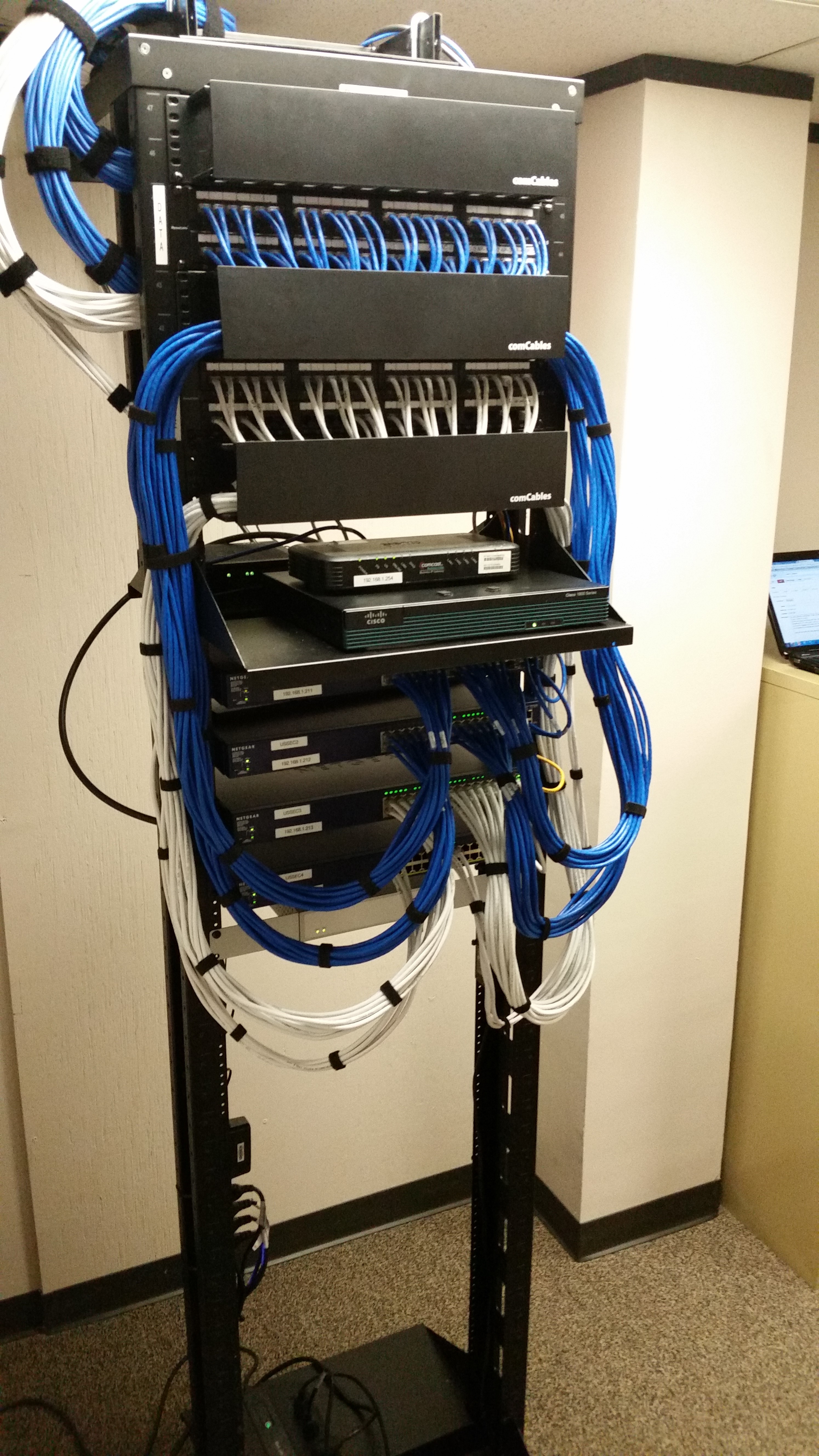
Click for BIG Picture for a picture of a Split Network.
FAST Discovery:
- Ask the client if just one phone is effected or are all phones being effected. If it is just one Phone Click Here
- Look on Comm Data at the clients internet speed under the “Accounts” tab.
- If the network is a split network (two internet accounts and two modems) one for the data and the other for the phones you will need to reboot the modem for the phones.
- If it can not be determined which modem is for the phones, reboot both modems, routers, switches and then move to the phones.
- Run a speed test on the clients computer and take notes. The speed test might not meet the advertised speeds but it needs to be close.
- Try to do a join.me session with the client so you can take control of the computer.
- Once you are on the clients computer go to the router by typing the IP Address 192.168.0.1 or 192.168.1.1 and log on to the D-Link using the admin account – Password is going to be Yes followed by the Community Number. (i.e. Yes0569)
- The D-Link will open to the “Status” page.
- On the left hand side of the page you need to click on “Internet Sessions” See bellow for help files on this subject.
- If you see an abundant amount of connections chances are that the client has some malware, spyware, or adware that is using the Internet connection in the background without their knowledge. Upon discovery of this you should contact Machine Logic and alert them to this issue.
- On that computer run a netstat from a cmd prompt to see how many connections the computer has.
- Do this on every computer and take note. You are looking for a computer that has an unusual amount of connections made to it.
FAST Troubleshooting 2 or more phones not operational:
- Ask the client if just one phone is effected or are all phones being effected. If it is just one Phone Click Here
- Look on Comm Data at the clients internet speed under the “Accounts” tab.
- If the network is a split network (two internet accounts and two modems) one for the data and the other for the phones you will need to reboot the modem for the phones.
- If it can not be determined which modem is for the phones, reboot both modems, routers, switches and then move to the phones.
- If this does not bring the phones back up connect one of the phones to the data side of the network.
- If the phone starts working on the data side of the network after following steps 1 though 3, a Tier3 CEG Agent will need to be notified and the ticket moved to that Agent.
- If the phone does not start working after following steps 1 though 3, a Tier3 CEG Agent will need to be notified and the ticket moved to that Agent.

A Split Network – White CAT5 Phones / Blue CAT5 Data. 2 Modems. 2 Routers. Multiple POE Switches. Multiple “regular” Switches.
Troubleshooting Infected Computers overloading the network:
- Restart the Modem – Router – and if they have a Switch reboot that as well.
- Follow the order of rebooting; Reboot (Modem First) next the Router and so on, let each device come up before restarting the next device.
- Call the ISP and discover if the connection is healthy. If the connection is not in a healthy state move ticket to Tier3.
- If the connection is healthy from the ISP’s side, contact Machine Logic and let them know that the computers are probably infected and give them all the details regarding the computers connections.
- Read below Help for the D-Link “Internet Sessions”
Troubleshooting a Slow Connection:
- Call the ISP and get pricing for an increase in bandwidth. For ISP Support Phone Numbers Click Here
- Tell the CM that you think the network needs more bandwidth to fix the problem with the intermittent phone issues.
- Send out an email to the CM and the RM with the price quotes.
- For Template Email Click Here
- Open an AI Ticket and then get approval for the upgrade.
- The new or upgrade contract Docusign should only be signed by a Tier3 or NIM.
- Move this ticket to Tier3
The Internet Sessions page displays full details of active Internet sessions through your router. An Internet session is a conversation between a program or application on a LAN-side computer and a program or application on a WAN-side computer.
If you see an abundant amount of connections chances are that the client has some malware, spyware, or adware that is using the Internet connection in the background without their knowledge. Upon discovery of this you should contact Machine Logic and alert them to this issue.
Help for the D-Link “Internet Sessions”
If you need instructions on how to connect to the D-Link 655 read Equipment – How to connect to the D-Link
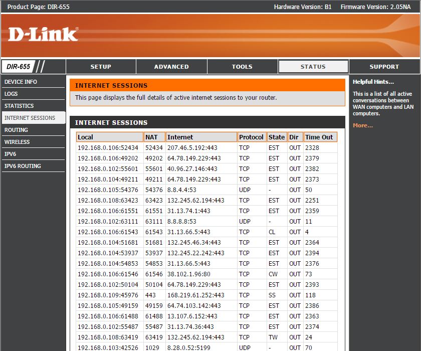
- Local: The IP address and, where appropriate, port number of the local application.
- NAT: The port number of the LAN-side application as viewed by the WAN-side application.
- Internet: The IP address and, where appropriate, port number of the application on the Internet.
- Protocol: The communications protocol used for the conversation.
- State: State for sessions that use the TCP protocol.
-
- NO: None — This entry is used as a placeholder for a future connection that may occur.
- SS: SYN Sent — One of the systems is attempting to start a connection.
- EST: Established — the connection is passing data.
- FW: FIN Wait — The client system has requested that the connection be stopped.
- CW: Close Wait — the server system has requested that the connection be stopped.
- TW: Time Wait — Waiting for a short time while a connection that was in FIN Wait is fully closed.
- LA: Last ACK — Waiting for a short time while a connection that was in Close Wait is fully closed.
- CL: Closed — The connection is no longer active but the session is being tracked in case there are any retransmitted packets still pending.
Troubleshoot up through the OSI Model:
The Open Systems Interconnection model (OSI model) is a conceptual model that characterizes and standardizes the communication functions of a telecommunication or computing system without regard to their underlying internal structure and technology. Its goal is the interoperability of diverse communication systems with standard protocols. The model partitions a communication system into abstraction layers. The original version of the model defined seven layers.
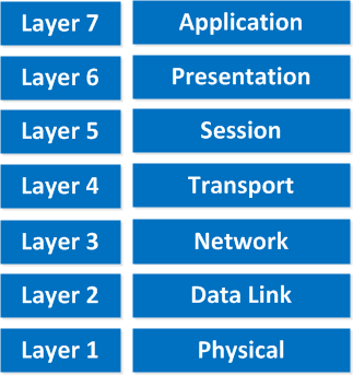
The Open Systems Interconnection Model
- Now that you have a firm understanding of the issue, track down its source. Conduct network troubleshooting following the OSI model.
- Start with the physical layer and work up to the application layer.
- Network problems are usually associated with the first three layers.
- This section of the article provides troubleshooting tips for firewalls, networking gear and the systems that connect to them. Unless otherwise noted, commands apply to both Windows and UNIX/Linux.
DEEP Discovery:
Physical Layer
The physical layer is one of the easiest to troubleshoot. It is also frequently overlooked. If there is a network connectivity problem, consider the following:
1. Ensure the equipment at the distant end is powered on.
2. Examine the cabling. Check for defects or damage. If a cable has been cut or stretched, it may not pass traffic. Check the connectors too. The cable may not be properly inserted into the connector. If the connector is not crimped properly, the wiring may not be making contact with it.
3. Keep in mind that the maximum length of an Ethernet segment is 300 feet. If a cable is too long, there may be intermittent connectivity problems, or it may not work at all.
4. Ensure that each cable connector clicks as it is inserted into the network port.
5. Check the network port indicator lights on each system. If a link light is out, there is an issue with either the network card or cabling.
6. Ensure that the proper type of cabling is in use:
a. Cabling between phone systems and network devices use a “straight through” cable. To examine the wiring, look closely at the clear connectors at each end of the cable. A straight through cable has an identical wiring layout on both sides.
b. Direct cabling between phone systems requires a CAT5 cable.
7. Finally, try swapping out the network cable with one that is known to be good or test it with different equipment.
Data Link Layer:
This is only to be ran by a Tie3 or lower Tier Agent during training.
At the data link layer, local communications occur by network port hardware addresses, also referred to as Media Access Control (MAC) addresses. Failures at this layer are usually caused by an improperly configured network port or a physical problem.
1.a. If there are network connectivity issues, check the Address Resolution Protocol (ARP) table.
arp -a
C:\Windows\system32>arp -a

Interface: 192.168.1.185 --- 0xb
 Internet Address Physical Address Type
 192.168.1.1 b0-fa-eb-d9-ee-f0 dynamic
 192.168.1.3 f8-bc-12-50-26-1e dynamic
 192.168.1.20 a0-d3-c1-d5-a7-c9 dynamic
 192.168.1.106 28-10-7b-28-8c-ae dynamic
 192.168.1.184 90-fb-a6-29-74-27 dynamic
 192.168.1.190 18-03-73-01-ea-11 dynamic
 192.168.1.199 d4-be-d9-de-a2-a4 dynamic
 192.168.1.200 d4-ae-52-d5-3a-a7 dynamic
 192.168.1.214 d4-ae-52-d5-3a-a7 dynamic
 192.168.1.215 d4-ae-52-d5-3a-a7 dynamic
 192.168.1.217 d4-ae-52-d5-3a-a7 dynamic
 192.168.1.219 d4-ae-52-d5-3a-a7 dynamic
 192.168.1.220 d4-ae-52-d5-3a-a7 dynamic
 192.168.1.221 d4-ae-52-d5-3a-a7 dynamic
 192.168.1.222 d4-ae-52-d5-3a-a7 dynamic
 192.168.1.255 ff-ff-ff-ff-ff-ff static
 224.0.0.22 01-00-5e-00-00-16 static
 224.0.0.252 01-00-5e-00-00-fc static
 239.255.255.250 01-00-5e-7f-ff-fa static

C:\Windows\system32>
1.b. The IP address of at least one system should be listed. If there are no systems listed, there is a problem at the physical layer (above).
1.c. From the arp command results above, determine if the MAC address matches the distant network port hosting that IP address. If the MAC address is incorrect, delete the offending ARP entry.
arp -d <IP address>
The ARP entry will be added automatically when network traffic arrives for that IP address. In most cases this occurs almost immediately. If the incorrect ARP entry appears again, there is a duplicate IP address on the network.
1.d. In some instances, two systems are linked in a high availability (HA) configuration. To ensure consistent service, if one system fails the other takes over automatically. This is accomplished by the standby system sending a gratuitous ARP broadcast across the local network (i.e., my MAC address answers for this IP address). If HA failovers are not taking place, the local router may have ARP caching enabled. To restore HA functionality, disable ARP caching on the router.
1.e. MAC addresses can also be used to determine the vendor of systems attached to the network. This can be useful in tracking down an offending system. To determine the vendor of a network port, visit the IEEE site at http://standards.ieee.org/regauth/oui/index.shtml. The search format is separated by dashes (i.e. 08-00-20).
2. Systems must be configured to auto negotiate or use the same speed and duplex settings. Otherwise there may be network performance issues or complete loss of connectivity. If these are the symptoms of your issue, confirm that network ports at each end of the wire are configured in the same manner (e.g. auto negotiate or 100 Mbps full duplex).
3. If there are intermittent or constant connectivity problems, use the netstat command to check the status of the network interfaces:
netstat -e
C:\Windows\system32>netstat -e
Interface Statistics

 Received Sent

Bytes 1547398080 3642122032
Unicast packets 53217876 47645240
Non-unicast packets 1499564 75776
Discards 0 0
Errors 0 0
Unknown protocols 0

C:\Windows\system32>
Errors are usually caused by defective network hardware so if a computer is having issues on the physical layer the phones can be effected dramatically more so.
4. It is possible that the hardware is fine and the interface is down within the operating system. Use the ifconfig command to determine the status of the interface:
ifconfig -a
dec0: flags=4023<UP,BROADCAST,NOTRAILERS,EXTERNAL> mtu 1500
inet 64.94.50.88 netmask ffffff00 broadcast 64.94.50.255
dec1: flags=2023<BROADCAST,NOTRAILERS,INTERNAL> mtu 1500
inet 10.0.5.1 netmask ffffff00 broadcast 10.0.5.255
In this example, the dec0 interface is “UP” and operational. The dec1 interface is down because ifconfig does not list it as “UP”.
If “UP” is missing from the ifconfig status, use ifconfig to bring it on-line:
# ifconfig dec1 up
5. The default Message Transmit Unit (MTU) setting is 1500 (see “ifconfig -a” output above).
a. If the MTU is set to something other than 1500, the network may run slowly. To set the MTU to a default of 1500:
# ifconfig dec0 mtu 1500
b. In the event that there are issues with VPN connectivity over a Cable or DSL connection, try setting the VPN client workstation to an MTU of 1400. The DrTCP utility can be used for this purpose (http://www.dslreports.com/drtcp).
6. During the boot process, Windows workstations typically use the Dynamic Host Configuration Protocol (DHCP) to obtain basic network configurations. DHCP servers usually serve up an IP address, DNS server settings, netmask and default gateway. To view active configurations, use the ipconfig command.
c:\> ipconfig /all
If this process fails, the workstation will not have a proper network configuration. This issue typically occurs in home environments when the workstation boots before the system providing DHCP services (usually a router or modem). The fix action is to release and renew the network configurations using DHCP.
c:\> ipconfig /release
c:\> ipconfig /renew
Network
In order to communicate across a network, each system needs an IP address, a default gateway and a network mask.
1. Confirm that each node on the network has a unique IP address. If a system boots and advertises an IP address that is already in use, the system previously using that address will respond, and the new system will shut down its own networking. Use the ipconfig and ifconfig commands to determine the IP address assigned to each interface (Windows and UNIX/Linux, respectively).
2. Each system sends network traffic to its default gateway. If the default gateway is incorrect or missing, network traffic will not flow. The only exceptions are manually configured static route entries. Determine if the default gateway is correct in the output of “netstat -rn”.
3. The network mask tells the system which devices are on its local network. All other traffic will have to go through a router. The most common network mask is 255.255.255.0. Current mask configurations can be displayed with the ipconfig and ifconfig commands. The topic of subnetting is too complex to discuss here. If you are uncertain about a network mask, contact your network administrator.
4. Try using the ping command between devices (when interacting with a CyberGuard firewall, this requires echo/ICMP rules with enable replies selected).
# ping 192.168.0.1
- From a client, can you ping the internal interface of the firewall?
- From the firewall, can you ping the client?
- From the firewall, can you ping the firewall’s default gateway?
5. If there are still issues with external connectivity, contact your ISP and ask them to test the line.
6. Denial of Service (DoS) attacks can degrade the performance of a system until it stops accepting network traffic. To determine what systems are connected, use the netstat command:
netstat
|
tcp
|
0
|
0
|
64.94.50.88
|
64.94.50.84.1112
|
ESTABLISHED
|
|
tcp
|
0
|
0
|
*.21
|
*.*
|
LISTEN
|
|
tcp
|
0
|
0
|
64.94.50.88
|
64.94.50.84.80
|
SYN_RECEIVED
|
This syntax is also a good method detect a SYN flood attack (SYN_RECEIVED).
7. If you suspect ICMP based virus traffic:
b. On Windows and Linux/UNIX systems, use the netstat command to view the ICMP protocol statistics:
# netstat -s -p icmp
8. If there are issues with routing, outbound traffic will not flow properly.
a. Check the routing table for erroneous entries:
# route print
b. Use the lookup feature of the route command to determine how it will route traffic based on an IP address.
# route -n lookup <IP address>
9. If there are external connectivity issues, determine if Dynamic Network Address Translation (DNAT) is enabled on the external interface of the firewall. If DNAT is not enabled, traffic cannot find a route back to your system unless a static NAT is in place.
Transport
On most firewalls, select enable replies in UDP and ICMP packet-filter rules. These protocols support ping, the Domain Name System (DNS) and syslog.
Session & Presentation
Issues rarely occur at the session and presentation layers.
Application
The application layer is where the client-server issues fall. This includes SMTP, POP3, HTTP, FTP, etc.
1. DNS supports many commonly used programs and services, including web pages and e-mail. DNS translates host names into IP addresses (e.g. www.google.com to 8.8.8.8). To confirm DNS functionality, use the nslookup command:
# nslookup www.google.com
It should respond with an IP address. If it does not, check your DNS server settings.
Additional DNS troubleshooting is beyond the scope of this article contact Tier3.
2. If all else fails, use the tcpdump command to troubleshoot:
# tcpdump -vvpni dec1 -s1514 -w /archive2/dec1.dmp host ip address (e.g. 192.168.0.23)
Tcpdump functions from the application layer down to the data link layer. If you are troubleshooting a proxy, you will need to run it on both sides. Tcpdump output is not for the faint of heart. I recommend viewing it with Ethereal (http://www.ethereal.com). The Windows version is Windump (http://windump.polito.it).
Resources: