Scope of Work Office Suite
The Scope of Work (SOW) is used as a way to insure a smooth Network Repair or even add a New Network to an office.
The Scope of Work will be referred to as “SOW” from this point on in this Article.
Quick Facts:
- All SOW documents are saved in the “Project Folder” that you are working on and need to be named appropriately; Example “The Breakers 1.5.16” .
- A SOW will be sent along with an email when requesting a Granite Tech to be on site.
- A SOW is easy to make using the Modules bellow.
- You will find all you need to create a SOW here (X:\Support Staff Resources\__New SOW) Alternitivly you can download a zip file with all the modules in it.
Click Here for all the SOW Modules in MS Word.
How to build a SOW
Building a SOW is easy when you understand it’s just like playing with building blocks!
- Download – SOW – Template located in (X:\Support Staff Resources\__New SOW) and add the following modules as you build the SOW document.
- Do a Save As on the SOW – Template in the project folder you are working from and rename it SOW – Name of Office.docx.
- Now work from the SOW you have just created.
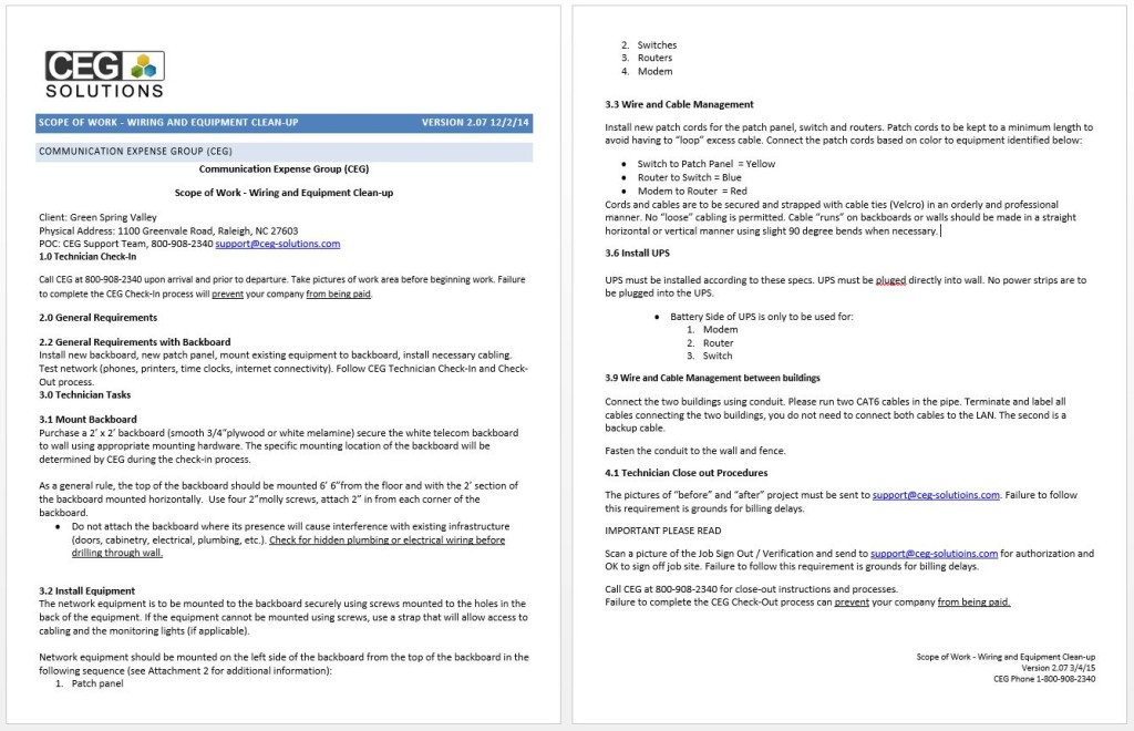
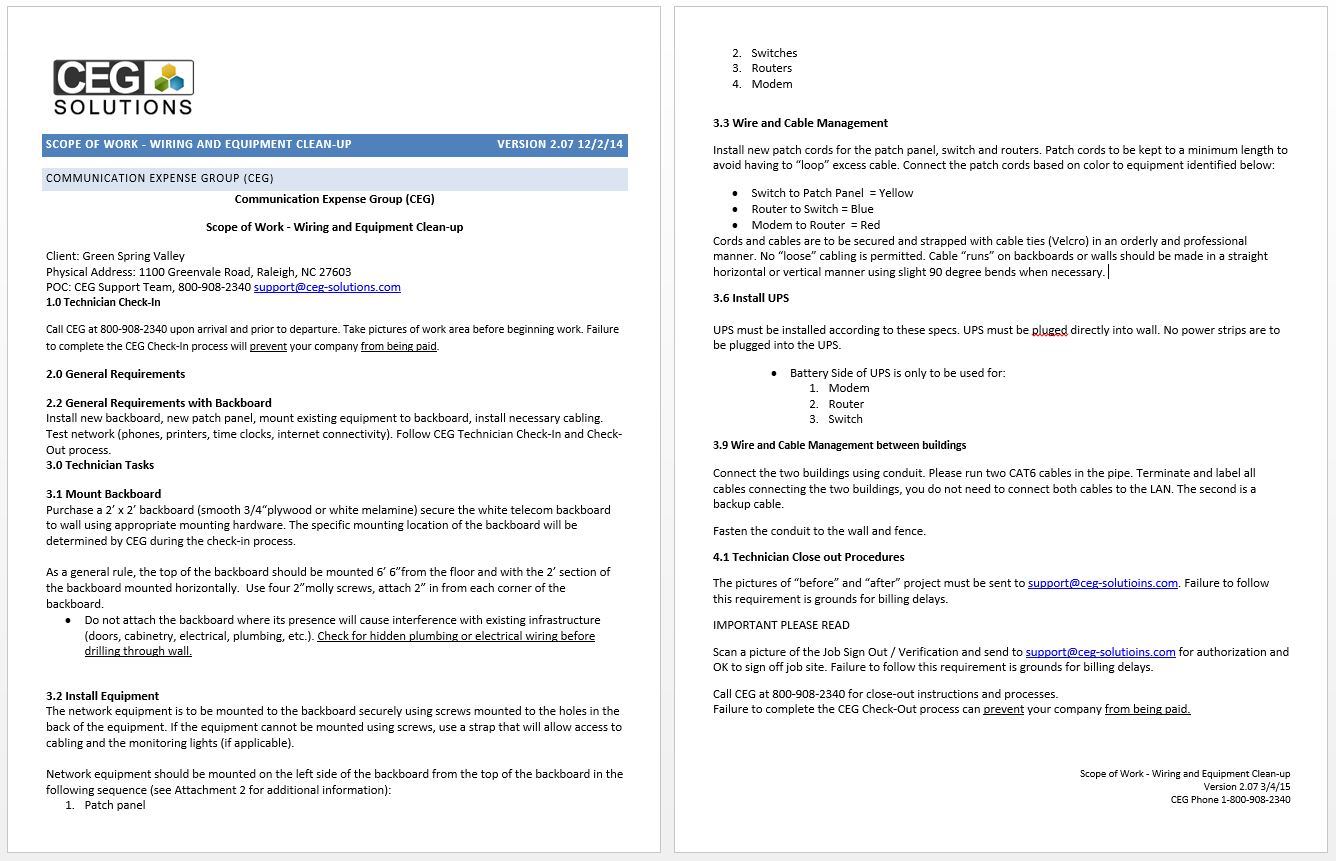
- The finnished SOW should look like this when you are done. Click Here For a Sample SOW Document.
- Replace Scope of Work – Description of Work Here with your own description of work requested.
- Now Copy and Paste the following Modules and Header to your SOW.
- In the SOW document copy and paste the Modules in the space designated for the Modules:Copy and Paste Modules in Space Bellow. —+— Copy and Paste Modules in Space Above.
Header Information:
Client: YES Communities – Name of Community goes here.
Physical Address: Address of Community goes here.
POC: CEG Support Team, 800-908-2340 support@ceg-solutions.com
This is the easy part! Simply pick any “Module” that you need for an install and add it to your SOW document.
Module Selection – 1.
1.0 Technician Check-In-Module
Call CEG at 800-908-2340 upon arrival and prior to departure. Take pictures before of network and surroundings and send the pictures to support@ceg-solutioins.com. Failure to complete the CEG check-in and check-out procedures can prevent or delay your company from being paid.
Module Selections – 2.
2.0 General Requirements-Module
Call CEG 800-908-2340 ask for New Install Manager (NIM) and supply the following info.
Your first and last name
Your email address
Your cell phone number
Your travel time
The company name you work for (Not Granite)
2.1 New Equipment or Supplies-Module
New Equipment or Supplies to be purchased are identified on Attachment 1.
2.2 General Requirements with Backboard-Module
Install new backboard, new patch panel, mount existing equipment to backboard, install necessary cabling. Test network (phones, printers, time clocks, internet connectivity). Follow CEG Technician Check-In and Check-Out process.
2.3 General Requirements for New Drop-Module
Install new drop and label. install necessary cabling. Test network (phones, internet connectivity).
2.4 General Requirements Split Network-Module
Technician will be installing new network equipment and drops in order to split the existing shared network to separate voice and data network. Test network (phones, printers, time clocks, internet connectivity). Follow CEG Technician Check-In and Check-Out process.
2.5 General Requirements-Module
Test network (phones, printers, time clocks, internet connectivity). Follow CEG Technician Check-In and Check-Out process.
2.6 General Requirements Standard-Module
Test network (phone internet connectivity). Follow CEG Technician Check-In and Check-Out process.
2.7 General Requirements Run Multiple Drops-Module
Run multiple drops to a designated desk. Test connection. Test Phone. Test Computers.
Module Selections – 3.
3.1 Mount Backboard-Module
Purchase a 2’ x 2’ backboard (smooth 3/4“ plywood or white melamine) secure the white telecom backboard to wall using appropriate mounting hardware. The specific mounting location of the backboard will be determined by CEG during the check-in process.
As a general rule, the top of the backboard should be mounted 6’ 6”from the floor and with the 2’ section of the backboard mounted horizontally. Use four 2”molly screws, attach 2” in from each corner of the backboard.
- Do not attach the backboard where its presence will cause interference with existing infrastructure (doors, cabinetry, electrical, plumbing, etc.). Check for hidden plumbing or electrical wiring before drilling through wall.
3.2 Install Equipment-Module
The network equipment is to be mounted to the backboard securely using screws mounted to the holes in the back of the equipment. If the equipment cannot be mounted using screws, use a strap that will allow access to cabling and the monitoring lights (if applicable).
Network equipment should be mounted on the left side of the backboard from the top of the backboard in the following sequence (see Attachment 2 for additional information):
- Patch panel
- Switches
- Routers
- Modem
3.3 Wire and Cable Management-Module
Install new patch cords for the patch panel, switch and routers. Patch cords to be kept to a minimum length to avoid having to “loop” excess cable. Connect the patch cords based on color to equipment identified below:
- Switch to Patch Panel = Yellow
- Router to Switch = Blue
- Modem to Router = Red
Cords and cables are to be secured and strapped with cable ties (Velcro) in an orderly and professional manner. No “loose” cabling is permitted. Cable “runs” on backboards or walls should be made in a straight horizontal or vertical manner using slight 90 degree bends when necessary.
3.4 Equipment Needed on Site by Technician-Module
- Telecom White Backboard
- Patch Panel
- 16 Port Switch
- All Appropriate Patch Cables
The Good the Bad and the Ugly…


3.5 Install Equipment without Telecom Backboard-Module
Equipment is to be placed in organized manner. Do not stack equipment. All equipment must be in ventilated environment. All equipment must be easy to access for user. Environment must be clean of old equipment and free of dust. Power cables must be reachable and organized.
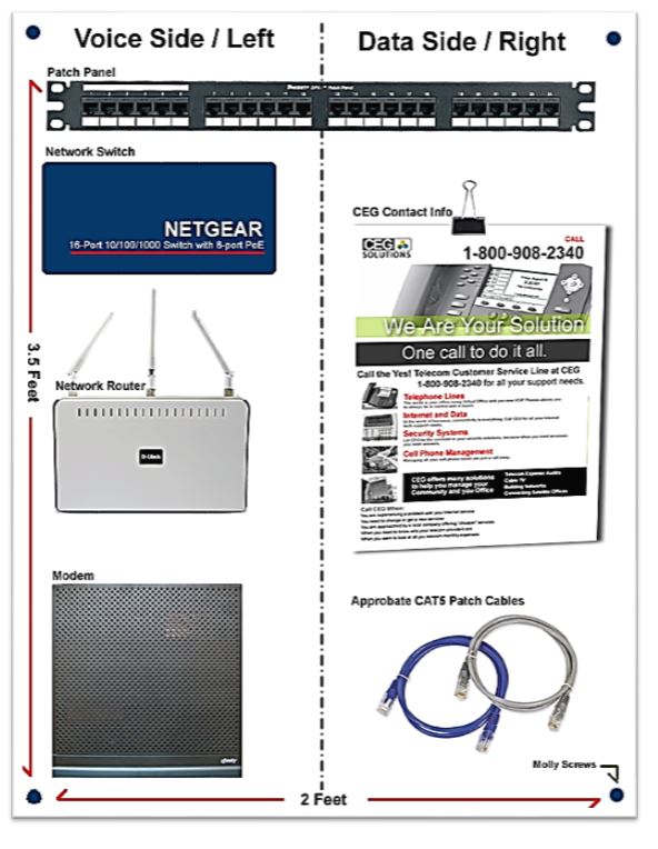
Click Here for large picture to paste on your SOW document.
3.6 Install UPS-Module
UPS must be installed according to these specs. UPS must be plugged directly into wall. No power strips are to be plugged into the UPS.
- Battery Side of UPS is only to be used for:
- Modem
- Router
- Switch
3.7 Wire and Cable Management for Drop-Module
Patch cords to be kept to a minimum length to avoid having to over “loop” excess cable.
Cords and cables are to be secured and strapped with cable ties (Velcro) in an orderly and professional manner. No “loose” cabling is permitted. Cable “runs” on backboards or walls should be made in a straight horizontal or vertical manner using slight 90 degree bends when necessary. Avoid running cable on outside structures (Wall in Office, Floor…).
3.9 Wire and Cable Management between buildings-Module
Connect the two buildings using conduit. Please run 2 (One Spare) CAT6 cables in the PVC pipe. Terminate and label all cables connecting the two buildings, you do not need to connect both cables to the LAN. The second is a backup cable.
Fence and wall install-Module
Fasten the conduit to the wall and fence no higher than 4 feet and no lower than 1 foot.
3.10 Printer Connectivity-Module
The network printer needs to be installed and configured to work on all the computers on the network.
Printers need to be connected to all computers on the LAN.
Not all computers need the printer to be set as the “Default” printer but all computer must successfully be able to print a “test sheet”. Latest driver should be used.
Module Selection 4.
4.1 Technician Close out Procedures-Module
The pictures of “before” and “after” the project must be sent to support@ceg-solutioins.com. Failure to follow this requirement is grounds for billing delays.
IMPORTANT PLEASE READ
Scan a picture of the Granite Job Sign Out / Verification Sheet and E-mail it to
support@ceg-solutioins.com for authorization and an OK to sign off job site. Failure to follow this requirement is grounds for billing delays.
Call CEG at 800-908-2340 for close-out instructions and processes.
Failure to complete the CEG Check-Out process can prevent your company from being paid.